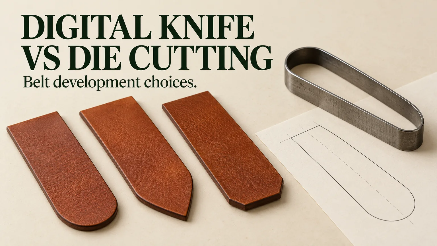
Digital knife cutting is often the more flexible route while a belt pattern is changing; die cutting can make sense once a repeatable shape justifies dedicated tooling. Neither automatically delivers better leather utilization, cleaner edges or a lower finished-belt cost. Compare the same material, approved pattern and accepted output, then include revision work, setup, handling and downstream finishing in the decision.
For a brand developing a belt collection, the useful question is not which machine is more advanced. It is which route keeps the current design decisions affordable without losing control of the part that reaches assembly. A sample cut from a digital file and a production strap cut with a die can belong to the same program, provided the change is qualified rather than assumed equivalent.
What should drive the choice?
- Pattern maturity: an unsettled tip, tab or keeper shape favors a route that can accommodate revisions.
- Accepted output: compare usable parts and completed operations, not cutting-head speed or press strokes.
- Material behavior: hold-down, tool condition and part placement matter whichever route is selected.
- Transfer control: approving a digital sample does not automatically approve the first die-cut production parts.
What changes between the two cutting routes?
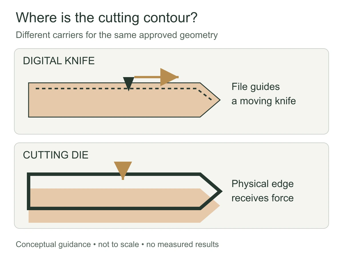
A digital knife system moves a cutting tool along a programmed contour. The shape is carried in a file; the actual cut also depends on the selected tool, cutting settings and how the material is held. A knife cutter is not a laser: the comparison here concerns mechanical cutting, not a heat-based process.
A cutting die carries the contour in a physical cutting edge. A press drives that tool through the material against a suitable cutting surface; ATOM’s swingbeam press documentation illustrates how cutting force and die-related setup belong to the process. Depending on the tool and operation, the die may define a complete component or only a feature such as the belt tip. Some belt programs therefore use more than one cutting route rather than making an all-or-nothing equipment choice.
Zünd’s L3 documentation provides a concrete digital-system example: it describes vacuum hold-down, projection-assisted placement, interchangeable tools and tool initialization. Those features show why “digital” describes a system, not just a file. They are not a statement that HongDing uses that model, or that its published machine specifications are finished-belt output figures.
Keep the operation boundary clear. A cut outline does not necessarily include adjustment holes, a buckle slot, splitting, edge finishing or stitching. If one quote includes several of those operations and the other includes only an outline, the prices are not comparable. Start with a drawing that identifies which features each operation creates.
Choose by the maturity of the belt pattern
When the design is still moving
Consider a fashion belt whose tip shape, width or decorative tab is still under review. A file-based route lets the development team revise the contour without commissioning a new shape-specific cutting die for every iteration. That is useful when the sample’s purpose is to resolve proportion or fit rather than prove the final production method.
The revision is not free of work. Someone must update the correct drawing, check scale and units, prepare the cutting path and examine the new part. An old file with the correct product name can still contain the wrong hole position or tip length. Ask for a revision reference that connects the drawing, cut part and sample feedback, not simply a filename ending in “final.”
Preserve what should not change. If the buyer only wants a rounder tip, the next sample should not silently change strap width, hole layout and buckle attachment as well. A narrowly defined revision makes it easier to judge whether the intended improvement actually occurred.
When the shape is stable
For an approved shape that will repeat, a dedicated die becomes a candidate because its preparation cost can be spread over repeated use. The relevant repetition is use of that particular tool, not the total number of belts in a mixed collection. Ten distinct shapes do not necessarily share the economics of one stable shape ordered in the same total quantity.
Die suitability also depends on what changes between sizes. A common tip tool might serve several strap lengths, while a complete shaped-belt outline may require separate tooling. Ask the factory to distinguish reusable features from size-specific contours. Do not assume every length needs a complete new die, or that one die can make the entire range.
A digital route can remain appropriate in production when variation, nesting flexibility or the actual workflow supports it. A die route can also be useful during development when suitable tooling already exists. “Digital for samples, dies for bulk” is a starting hypothesis, not a production rule.
Compare the operations on equal terms
On a narrow screen, scroll the table to see both routes.
| Decision | Digital knife route | Die route |
|---|---|---|
| Shape change | Revise the file and qualify the new cutting path. | Assess whether the existing tool can be modified or must be replaced. |
| Repeat orders | Retain the approved file and relevant setup information. | Retain an identified tool with its revision and condition history. |
| Material placement | Use the actual placement, registration and hold-down method. | Control die positioning, orientation and material support. |
| Small details | Trial tool access, turning behavior and cut completion. | Check tool construction, feature spacing and clean release. |
| Cost comparison | Include preparation, cutting, handling and accepted output. | Include tooling, setup, handling, upkeep and accepted output. |
The table deliberately avoids a universal quantity threshold. A simple strap, a shaped waist belt and a small decorated tab create different workloads. Even within one style, changes in leather article or component thickness can alter the appropriate setup. Use the factory’s project-specific trial and quote to decide where the economics turn.
Cut quality: look beyond the top-face outline
Two parts can look similar from above but behave differently during edging or assembly. Check the edge face, corners and feature relationships as well as the overall silhouette. The following checks are a buyer-oriented troubleshooting method, not a diagnosis based on appearance alone.
A wandering or distorted contour
If a long edge departs from the approved pattern, compare the part against the same reference without pulling it into position. Then ask whether the deviation repeats at the same location. A repeatable mismatch directs attention toward the file, tool or setup; variable distortion also raises questions about material movement, placement and handling. The pattern of the error helps the factory choose what to investigate.
Do not solve a movement problem by casually enlarging the design tolerance. First establish whether the part was cut to the approved contour under the agreed measuring conditions. If the material changes shape after release, the development team needs to distinguish cutting accuracy from the behavior of the material itself.
A ragged, incomplete or visibly uneven edge
Review both faces and the edge before edge paint or burnishing conceals the original condition. Ask the cutting team to examine tool sharpness, penetration, support and material restraint. For a die route, include the condition of the die and cutting surface; for a digital route, include the blade and cutting-path settings. The correct remedy depends on the observed cause, not the equipment label.
A finishing operation can remove or cover some surface irregularity, but it should not become an unpriced rescue process. Compare the approved edge after the intended finishing steps. A route with a lower cutting charge may be less attractive if it adds avoidable trimming or causes unacceptable variation at the finished edge.
Holes or slots that do not align with the outline
If the contour is cut in one operation and the holes in another, their relationship depends on the second operation’s positioning reference. Measure a hole from the agreed datum, such as the strap centerline or a defined end, rather than from whichever nearby edge is convenient. A correct outline does not prove correct hole registration.
For the assembled belt, review the buckle attachment and adjustment area together. A slot that looks acceptable as an isolated cutout may not provide the intended movement when the strap is folded and fixed around hardware. Our hole-spacing and tip-shape guide addresses the finished-belt relationships; this cutting comparison concerns how those approved features are reproduced.
Material utilization is a separate result
A digital system’s ability to arrange shapes does not make every arrangement acceptable. Leather has usable boundaries, appearance variation and zones the project may exclude. A long belt strap needs uninterrupted length in an acceptable direction. Rotating it into an available gap may improve the drawing’s apparent utilization while producing the wrong part for the approved belt.
The same principle applies when an operator positions a die. Agree what constitutes an acceptable visible surface and where variations may be allowed before comparing output. Otherwise one route can appear more economical simply because it accepts material the other rejects.
Keep this question distinct from machine efficiency. Compare accepted parts from equivalent material inputs and the same placement restrictions. Record useful recovered components separately if, for example, keeper pieces are cut from spaces that cannot accommodate long straps. The existing leather cutting yield guide explains the measurement bases; there is no need to invent a new yield percentage for each cutting method.
Build a cost comparison that survives the next revision
Request the same scope from both routes. A useful comparison separates a one-time preparation or tooling charge from recurring processing cost, then identifies what would trigger a new charge. Include size variants and the changes still open, rather than quoting an imaginary finished design.
- Preparation: drawing cleanup, file preparation, tool manufacture and initial setup, as applicable.
- Running work: material positioning, cutting, part removal and the operations actually included.
- Quality-related work: agreed checks, reject handling and any finishing needed to reach the same accepted condition.
- Future changes: revision, replacement, storage and maintenance responsibilities for the selected route.
An illustrative comparison can use total route cost divided by accepted parts, provided both totals cover the same operations. If dedicated tooling is included in one total, state whether it is charged entirely to the first order or allocated across an agreed program. Do not allocate it across speculative future orders and present the result as the price of the confirmed order.
Time needs the same discipline. Cutting-head movement or a press cycle is only one part of elapsed production time. Loading, positioning, unloading, sorting and later operations may change the practical comparison. Ask for a plan covering the actual order rather than converting a machine brochure’s maximum speed into belts per day.
Qualify a sample-to-production route change
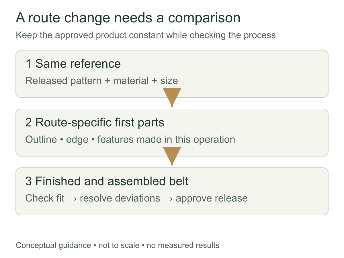
Consider an illustrative development program: a brand approves a digitally cut shaped tip, then receives a proposal to use a die for repeat orders. The approved visual idea can remain unchanged, but the production route introduces a new physical tool and setup. Treat the first die-cut parts as a transfer check, not as a replacement design review.
- Identify the common reference. Match the released drawing, size, material article and approved sample. Resolve discrepancies before interpreting the trial.
- Compare cut parts. Check outline, width, tip symmetry, edge condition and any features made in that operation under agreed measurement conditions.
- Finish and assemble. Use the intended edge process, hardware and construction. Confirm that the apparent match survives the remaining operations.
- Handle a mismatch deliberately. Hold the affected output, identify whether the cause is geometry, setup, material or a later operation, and compare the corrected parts again before release.
For repeat production, keep the approved reference available at the relevant checks. A first part establishes the starting condition; it does not prove that tool wear, material changes or setup drift cannot affect later output. Agree which characteristics will be checked during the run and who can authorize changes or release after a correction.
HongDing’s development support includes material and hardware coordination, sampling, revisions and production transfer. Its business roots date to 2004, with the current Hong Ding company identity formed in 2010. The value of that experience in this decision is connecting the cut component to the whole belt—not treating the cutting method as a substitute for evaluating fit and finish. The exact equipment route remains project-specific.
Questions before committing to a route
Does a digital cutter eliminate tooling?
It can eliminate the need for a dedicated physical outline die for the operation being cut. It still uses cutting tools and consumables, and other belt operations may require punches, fixtures or dedicated tools. Define which operation the claim covers.
Can a revised file be sent straight to production?
Not simply because it opens correctly. Check the released revision, scale, material and intended features, then review the resulting part. File readability and product approval are different checks.
Should a buyer specify the machine brand?
Usually the buyer’s first task is to define the required part and its accepted condition. If a particular process is essential, explain why and agree it explicitly. Otherwise evaluate the proposed route through representative parts and the complete belt rather than a machine name alone.
Discuss the next belt sample
Share the current drawing or reference image, the shape details still open and what you expect to repeat. HongDing can discuss the material, construction and sampling questions before a cutting route is confirmed. A complete tech pack is helpful, but it is not required to start that conversation.