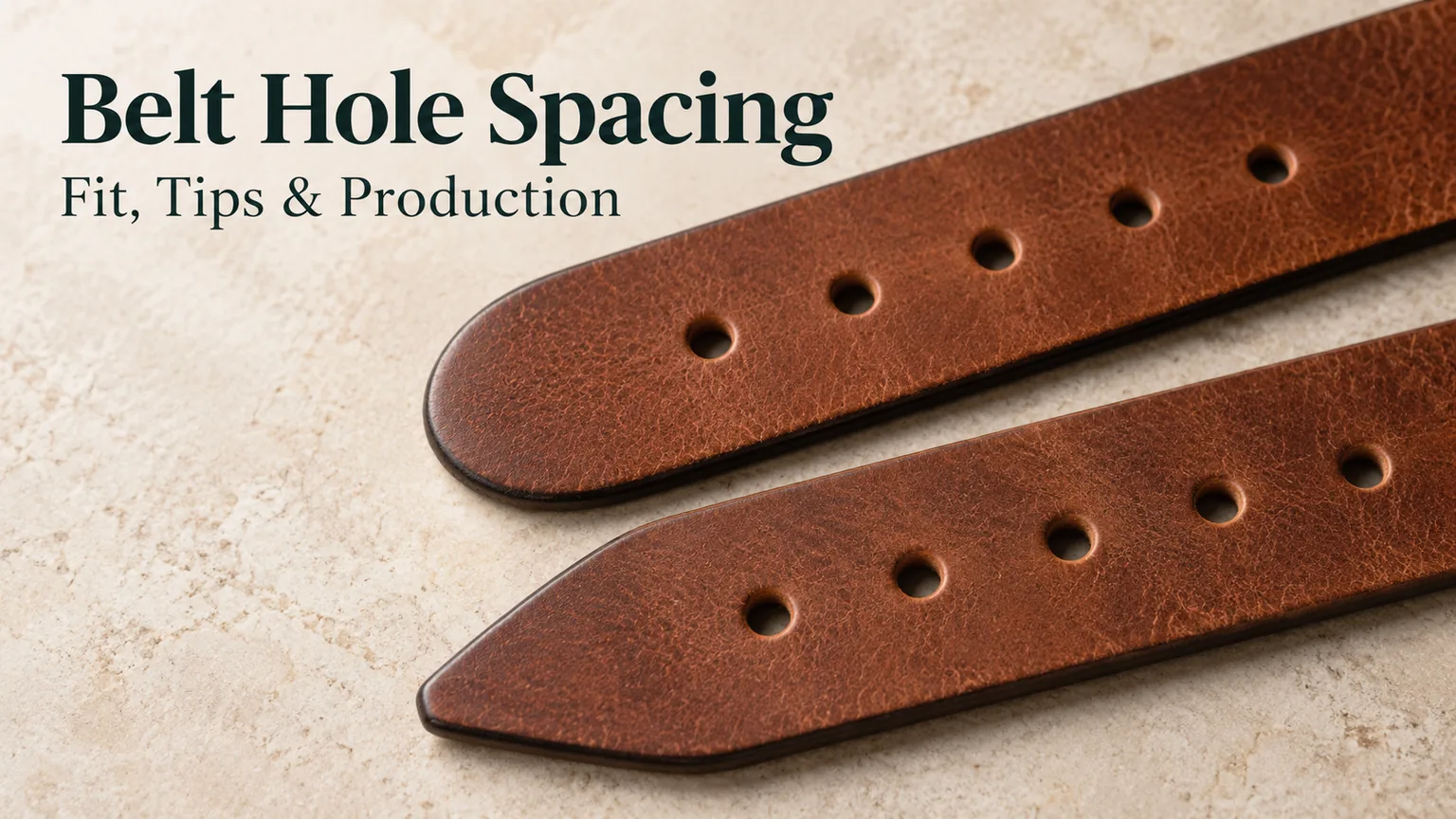
Belt hole spacing is the center-to-center distance between adjustment holes. For production, that number works only when the drawing also defines the buckle measuring point, the nominal-size hole, the number of holes, and the distance from the last hole to the tip. Choose these dimensions together: a belt can measure correctly at its middle hole yet leave too little tail at its largest setting or an awkwardly long tail at its smallest.
This guide covers conventional prong-buckle belts for brand and retail development. It does not prescribe one hole pattern for every belt. Ratchet tracks, friction closures, and woven straps need different adjustment specifications. If you are translating a consumer size label into a production measurement, start with our belt size and measuring guide; the work here is turning that fit decision into a repeatable hole-and-tip layout.
Start with a named buckle datum, not “belt length”
A datum is the reference point from which a dimension is measured. On a belt drawing, “length 900 mm” is incomplete unless both endpoints are clear. The strap fold, the buckle’s functional bearing point, and the outside edge of a decorative frame are different locations. Changing between them shifts every hole even when the number on the specification stays unchanged.
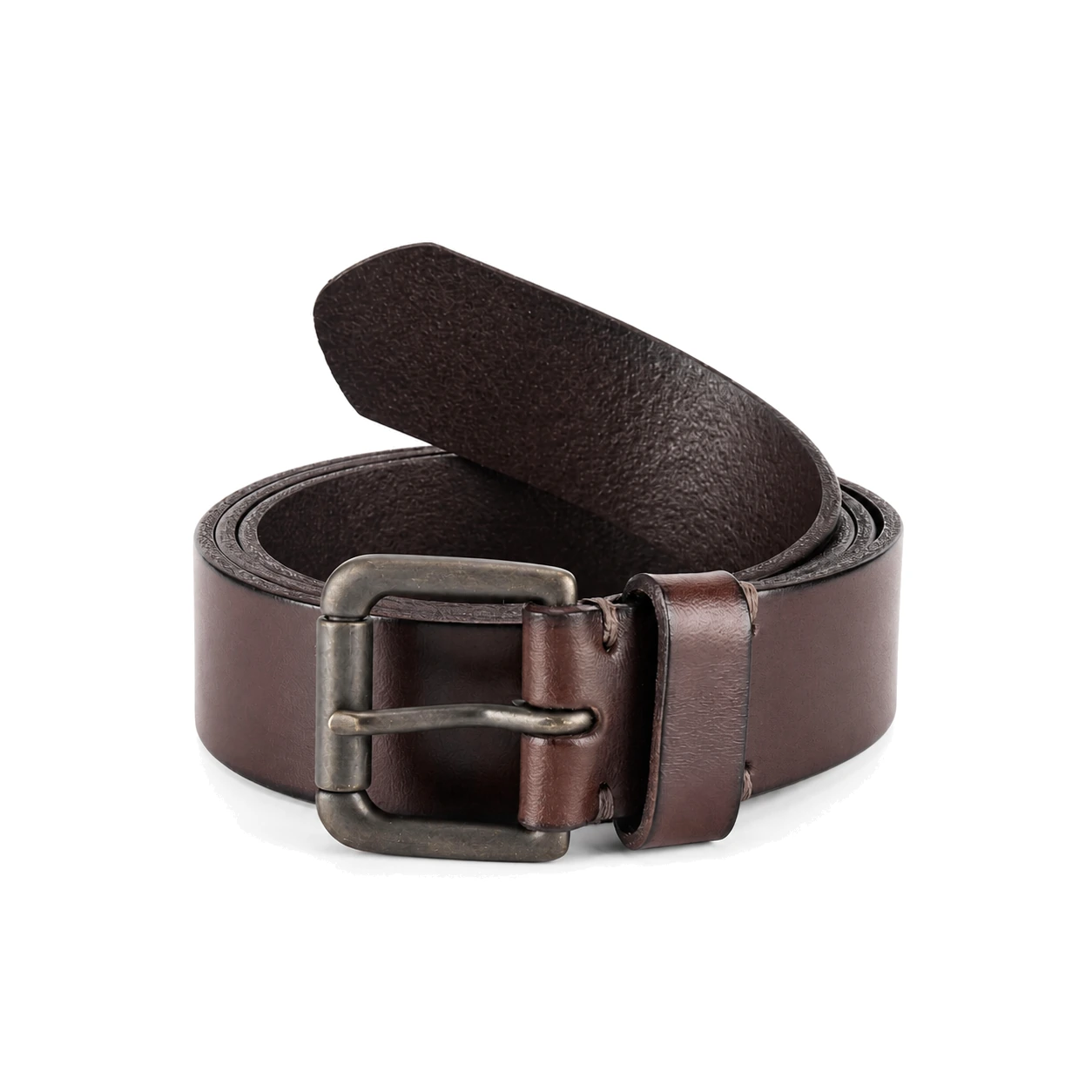
Photograph the assembled buckle and mark the selected measuring point on that photograph. Then identify the center of the hole that represents the labeled size. Keep the same convention in the drawing, sample report, inspection sheet, and customer size guide. Where an existing retail convention must be preserved, work backward from that convention rather than replacing it with a factory’s preferred shorthand.
The distinction matters when a brand changes hardware. Two buckles with similar external dimensions may have different bar positions or prong geometry. A replacement can alter the effective fastening circumference without changing the strap blank. Compare the closed assemblies, not just the open straps. If the new buckle changes fit, decide whether to shift the hole group, change the labeled size relationship, or reject the substitution.
Also separate finished size length from cutting length. Cutting length includes material consumed by the buckle attachment and the tail. Fold construction, lining, and fastening method can change that consumption. The cutting instruction belongs to the approved construction; it should not be inferred by adding a habitual allowance to every labeled size.
Spacing sets the adjustment step; hole count sets the range
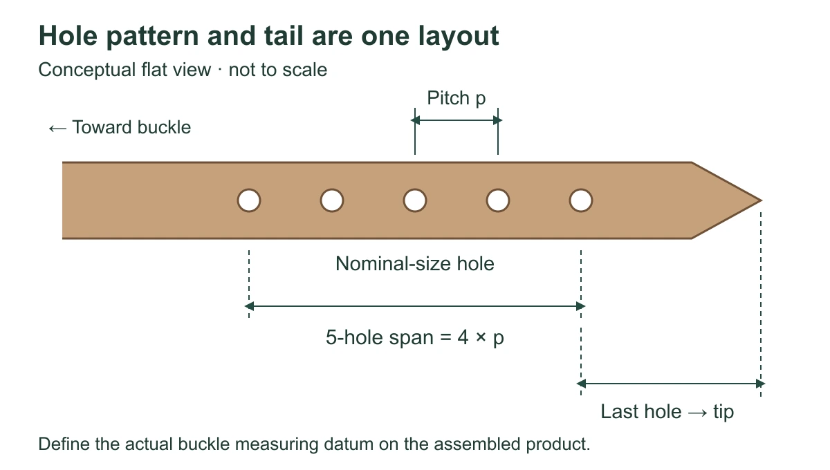
Smaller center-to-center spacing gives finer adjustment. More holes extend the range only if their locations extend farther along the strap. These are related but different design decisions. Adding holes inside an unchanged range improves choice between positions; adding holes outside the range changes the smallest or largest fit and the remaining tail.
For a straight row of equally spaced holes, the distance between the first and last hole centers is (number of holes − 1) × spacing. With an odd number centered on the nominal-size hole, half that span sits on either side. With an even number, specify which hole or which midpoint defines the nominal size; the phrase “middle hole” cannot resolve it.
Do not silently interchange 25 mm and one inch. One inch is 25.4 mm, so four one-inch intervals total 101.6 mm, not 100 mm. The difference may or may not matter to a particular product, but the drawing should choose one master unit and derive the other. Otherwise a metric punching tool and an inch-based inspection sheet can disagree while each operator believes the work is correct.
Decide spacing against the actual wearing situation. A belt over a dress may need different adjustment behavior from a jeans belt worn through loops. A stiff strap can feel more restrictive between two positions than a flexible construction. Elastic movement can also make a static hole range a poor description of wearing fit. Assess the finished assembly on the intended garment and at the intended waist or hip position.
More holes are not a free substitute for a size range. On small wearers, a long multi-hole strap can create excessive loose tail. On the largest setting, the same belt may barely reach its keeper. For a retail program, compare a small number of properly graded sizes with an extended-hole option, including appearance, labeling, and the complexity of stocking each choice.
Use one calculation to catch tail problems before sampling
Let C be the distance from the approved nominal-size hole center to the physical tip, p the hole pitch, and k the number of pitch intervals from the nominal-size hole to the last hole toward the tip. The remaining strap from that last hole to the tip is C − k × p. This is a flat-layout check, not a complete prediction of how much tail remains visible after fastening.
In an illustrative five-hole layout, C = 150 mm and p = 25 mm leave 100 mm beyond the last hole. Keeping the same tip while changing to seven holes leaves 75 mm. That arithmetic flags a keeper-engagement question before a sample is cut. It does not establish a minimum tail allowance: buckle path, keeper placement, strap thickness, and garment loops still have to be tested together.
Choose the tip around threading, appearance, and edge construction
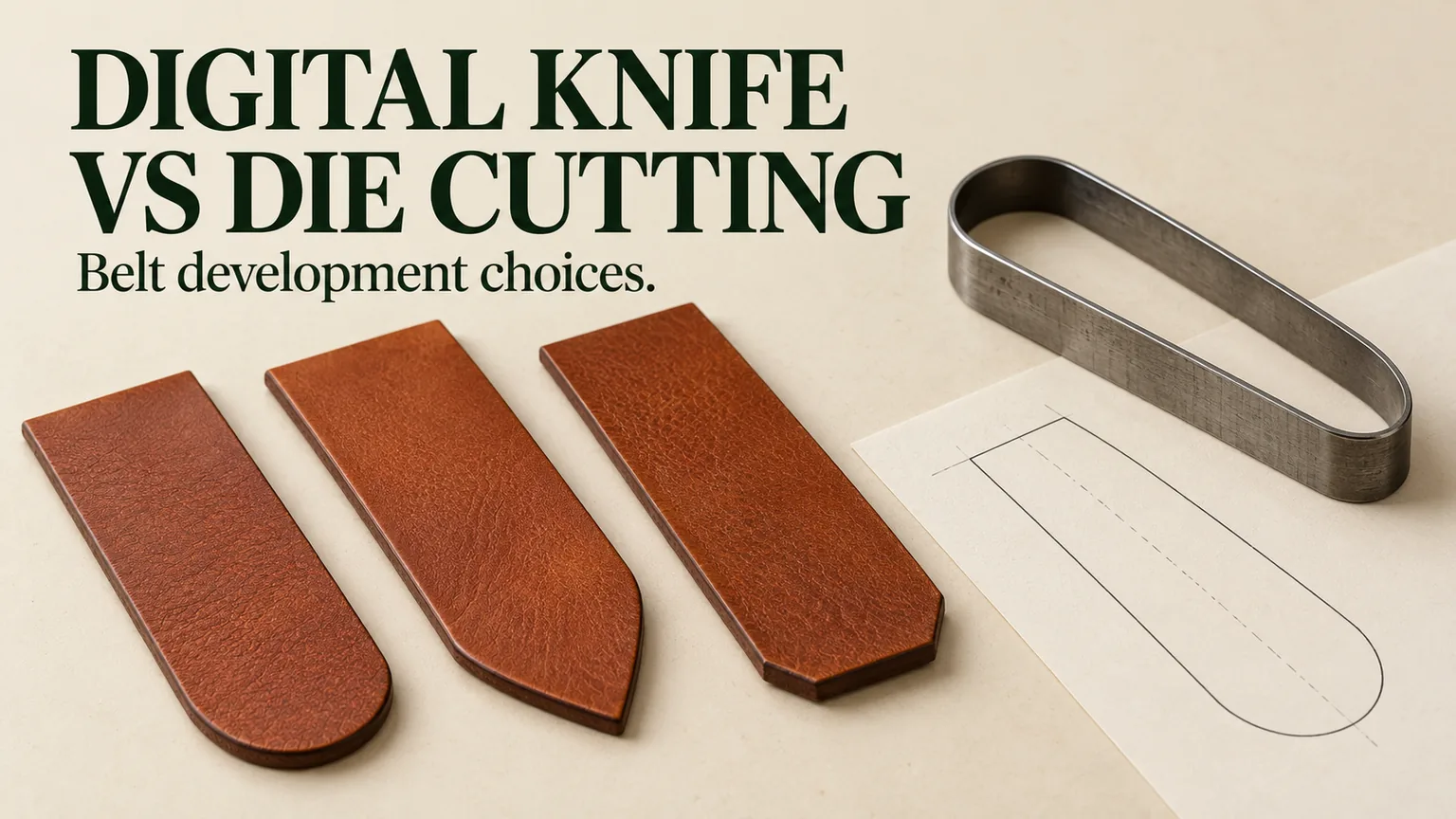
The tip is not merely the outline at the end of the strap. It is the leading edge pushed through the buckle, keeper, and garment loops. Its shape, thickness, stiffness, and finish determine whether that motion feels controlled or catches. A sharp-looking outline on a drawing can become a blunt, bulky end after lining, edge paint, or a metal tip is added.
| Shape | Useful characteristic | Sample check |
|---|---|---|
| Rounded | A continuous curve avoids pronounced corners. | Check the finished width and thickness through the keeper, not just the cut outline. |
| Tapered or pointed | A narrower leading end can help start threading. | Check that the point stays firm and the narrowing does not crowd the outer hole or stitch line. |
| Squared or lightly clipped | A geometric end can suit a restrained design. | Check corner catching and edge coverage during repeated threading. |
| Metal-tipped | Hardware defines the end and adds a distinct visual weight. | Check attachment, clearances, edges, and contact with other hardware. |
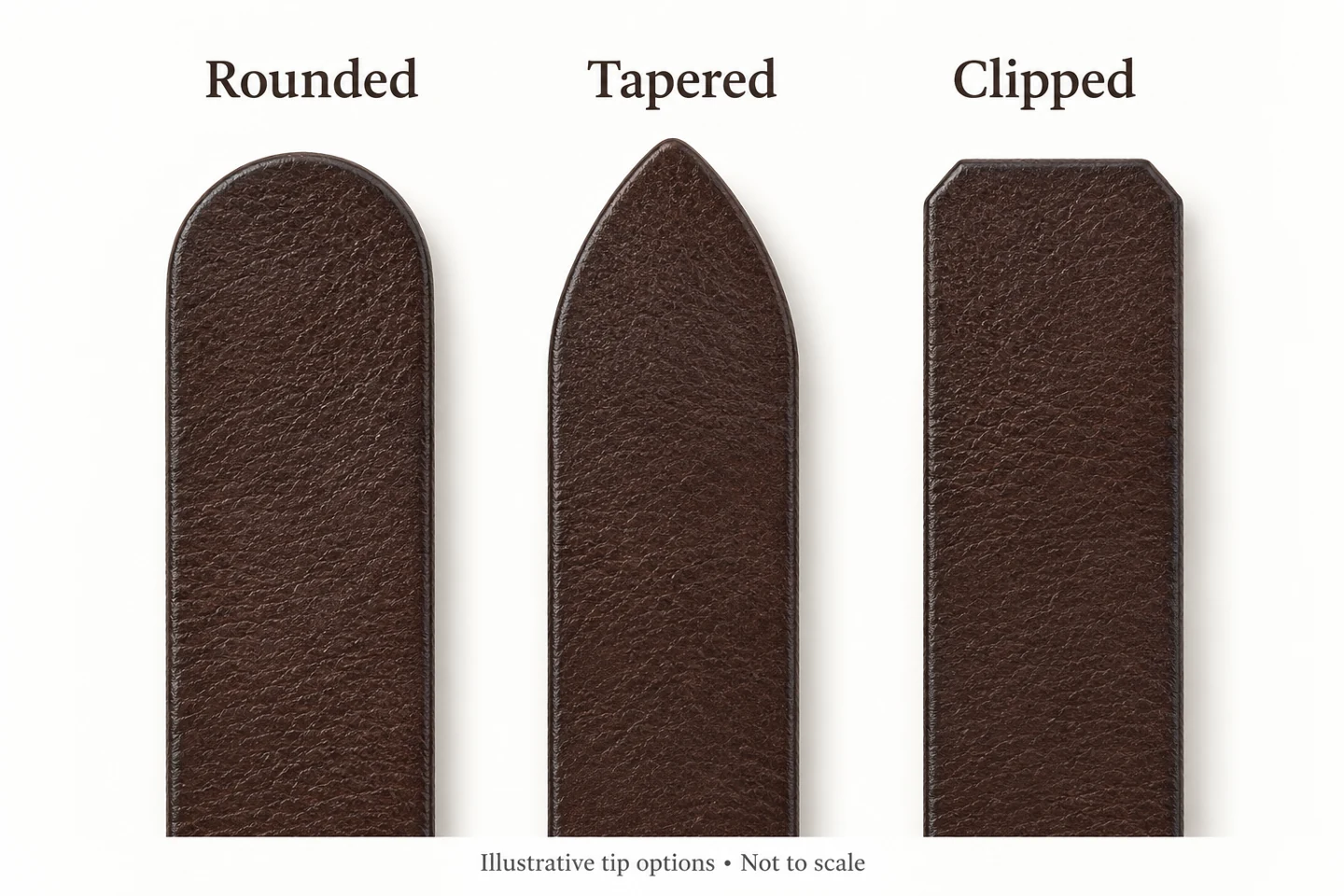
A taper can reduce the width presented at the entrance to a keeper, but it does not solve excessive thickness. If the end stops when the full-width section enters, examine the keeper opening and the compressed layer stack. Removing more material from the point alone may weaken the end without fixing the actual interference.
For stitched belts, review how the seam turns around the end. The seam needs to follow a practical path without crowding the edge or colliding with the last adjustment hole. On a lined or laminated belt, inspect whether the end exposes a layer transition or begins to separate after threading. On painted edges, check coverage and corner wear rather than judging only a pristine flat photograph.
Tail length should be approved at three settings: smallest, nominal, and largest. At the smallest setting, examine where the surplus tail lands, whether it stays captured, and whether it conflicts with a garment loop. At the largest, check that enough tail remains to use the intended keeper arrangement. At nominal fit, assess the silhouette the brand expects customers to see most often.
A floating keeper may help manage surplus, but it adds another component and does not excuse a poorly chosen strap length. Likewise, moving a fixed keeper changes threading and visible tail behavior. Treat either change as an assembly revision, with another fit check, rather than an independent cosmetic adjustment.
Hole size and shape must match the working prong
Hole pitch describes position, not opening size. Specify diameter for a round hole or length, width, and orientation for an elongated opening. The prong must enter and leave without unreasonable force, but excessive clearance can allow visible movement and concentrate wear differently around the hole. Approval therefore needs the actual buckle, not a nominal prong diameter taken in isolation.
A prong approaches the strap along an angled path as the belt is fastened. The geometry changes with buckle design and strap thickness. An opening that accepts the prong on a loose flat strip can still bind when the assembled belt is curved and loaded by normal fastening. Conversely, an oversized slot may look acceptable open but allow the buckle to sit unevenly in use.
Evaluate the surface around the opening as well. Punching removes material; worn tooling, poor support, or an unsuitable setup can leave ragged fibers, an incomplete cut, or a distorted edge. In multilayer constructions, inspect the back and layer interfaces, not only the visible face. A clean-looking upper opening does not confirm that the lining has been cut and cleared properly.
Keep the row aligned to the intended strap centerline. An off-center row can make the prong pull the belt asymmetrically or look visibly misplaced beside stitching and embossing. When a design intentionally offsets the holes, show that offset explicitly. Do not allow an inspection team to “correct” an approved asymmetric design by applying an assumed centering rule.
Closer holes require more than a fit preference
Reducing spacing while leaving hole dimensions unchanged reduces the material remaining between openings. Enlarging the holes has the same consequence. That does not establish a universal safe distance, because material, layers, width, and loading differ, but it identifies what needs validation. Compare the revised pattern with the approved construction through fastening and the relevant agreed strength or repeated-use evaluation.
If a sample shows elongation, first distinguish its location and mechanism. Uniform elongation at the occupied hole suggests a different issue from tearing between adjacent holes or an opening positioned too near a tapered edge. Record the loaded hole, sample construction, buckle revision, and observed damage. “Hole problem” is too broad a diagnosis to justify changing pitch, material, and tooling simultaneously.
Make the drawing measurable and the approval transferable
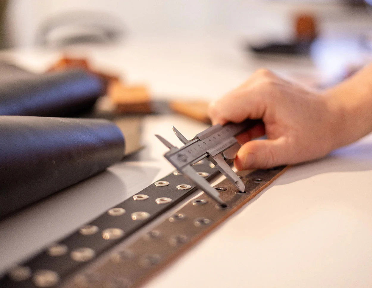
A practical production specification separates the dimensions that control fit from those that control appearance and assembly. It also states how to measure them. Use a flat, untwisted belt without stretching it; define how the buckle is positioned and whether a particular conditioning or settling procedure applies. A soft strap pulled tight by one inspector and laid relaxed by another will not produce a useful comparison.
- Fit: buckle datum to nominal-hole center, plus the approved size grading.
- Pattern: hole count, pitch, group location, opening dimensions, and centerline relationship.
- Tail: nominal-hole-to-tip and last-hole-to-tip relationships, with the approved tip template.
- Interfaces: buckle and keeper revisions, strap thickness at the working region, and threading behavior.
- Acceptance: drawing tolerances, visual references, measurement method, and agreed functional checks.
Tolerances should reflect the intended fit and demonstrated process capability. Avoid copying a tight number from another product simply because it looks precise. Equally, a loose total-length tolerance cannot absorb an unacceptable shift in the hole group. Agree critical dimensions separately, then check whether their combined variation still permits the buckle and tail to function at both end settings.
Measure hole locations from a common datum as well as checking adjacent pitch. Four intervals can each be near their allowed limit while the final hole drifts farther than expected. A setup check against the complete pattern helps distinguish a displaced hole group from cumulative spacing variation. If the entire group is shifted, correcting the pitch will not restore the nominal fit.
At sampling, compare more than one size. A middle-size sample can conceal an excessive tail in the smallest size or an altered tip-to-hole relationship in the largest. The size set need not duplicate every development exercise, but it should demonstrate that grading moves the intended dimensions while preserving those that are meant to remain constant.
From an approved sample to a repeat order
Keep the approved physical reference with its drawing revision and buckle identity. At production setup, compare the first pieces with both the reference and the dimensional record. Repeat the relevant check after a punch, fixture, material build, or hardware change. This connects the sample’s fit to the process that makes subsequent units instead of treating one attractive sample as proof of an entire run.
If an in-line check finds the whole hole group displaced, hold the potentially affected pieces back to the last accepted check and confirm the fixture datum before restarting. Separate already-punched straps from blanks that can still use the corrected setup. Adding another hole is not automatically an acceptable repair: it changes the pattern and may leave weakened or unwanted openings. Record the affected quantity, proposed disposition, and buyer approval where needed. Release corrected production only after the new first pieces pass the dimensional and fastening checks; keep that evidence with the lot.
HongDing’s development and manufacturing scope includes material and hardware coordination, sampling, punching, edge work, and dimensional checks. For this decision, that coordination is useful because a request such as “add two holes” can affect the tail, keeper, and tip construction at once. Our manufacturing review can connect those changes to the approved belt route rather than treating the hole row as a separate decoration.
For a repeat order, retain the approved layout even when a supplier proposes a visually similar buckle or a replacement leather article. Review what changes at the fastening interface before accepting the substitution. A replacement that looks the same in a catalog is not enough to establish that size labels, hole positions, and consumer fit remain equivalent.
Turn your fit reference into a production layout
Share a reference belt or a clear image, the intended wearing position, and any size convention you need to preserve. If you already have a buckle, include its dimensions or a sample. Discuss the layout with HongDing so the hole pattern, tip, and keeper questions can be resolved together before the design is released.